S6 Use prototyping techniques for testing circuits
Initial skills rating *
Oh dear this is another thing I have never done before. I have a lot of work to do. Where do I even start?
Introduction to protoboards
I have never seen a protoboard before.
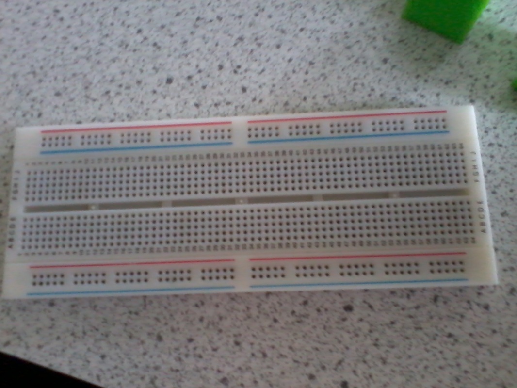
Protoboards have metal copper strips beneath the plastic surface, these conduct electricity to the discrete components in the same way as a track on a PCB. The important thing to remember is where the copper strips are in relation to the holes.
Looking at the picture of the protoboard at the top running from left to right would be four strips of copper. two one above the other between the red and blue lines. this is repeated at the bottom again between the red and blue lines. Beneath the remaining holes are more copper stips but this time they run vertically and are broken in the middle, The holes have numbers and letters so that the pin holes can be identified in the same way as the grid squares on a map.
Red rows are the + rows
Black rows are the 0V rows
Single core wire is best used for making up test circuits when using protoboards as it is more rigid and will push into the holes easily. Multi strand wire would be more difficult because the wires would spread apart.
Multi strand wires are used for products because they are more flexible and will therefore look neater
Multi strand wires are used for products because they are more flexible and will therefore look neater
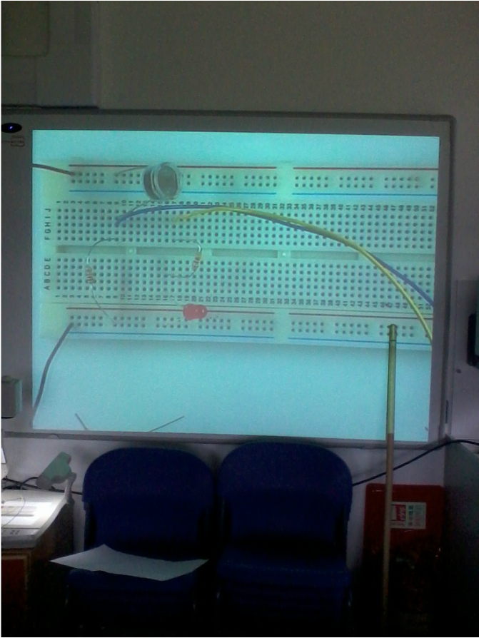
As can be seen in the image above there are many ways of positioning the components but the things to remember are:
only one put one end of each component per hole.
So remember NO HOLE SHARING!
Although strands of plain wire can be used to complete your circuit only use what you really have to.
only one put one end of each component per hole.
So remember NO HOLE SHARING!
Although strands of plain wire can be used to complete your circuit only use what you really have to.
Simple circuit
Starting to use protoboards for very simple circuits
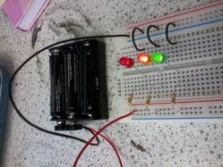
Bulbs in series
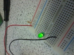
Using a protoboard to wire lights in both series and then parallel makes it easy to see the effects on the light emitted.
In a series circuit the currant is shared between the bulbs resulting in dim lighting. In this case the 3volts from the battery was shared giving each bulb approximately 1 volt each minus anything lost due to natural loses within the circuit.
In a series circuit the currant is shared between the bulbs resulting in dim lighting. In this case the 3volts from the battery was shared giving each bulb approximately 1 volt each minus anything lost due to natural loses within the circuit.
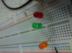
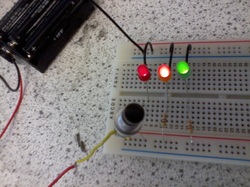
Bulbs in parallel
Whereas when the bulbs are mounted in series each bulb receives the full circuit voltage. The full three volts would be too much for the LEDs which only have a 2.5 volts rating. It is important to use the resistors to protect them from too much currant.
Starting to make a Darlington pair
Starting to make a Darlington pair. Which I never finished! It is only looking back I realise how silly this is. I have spent the year feeling panicked that I have not done everything whereas it would be better to do a little bit less but have finished more.
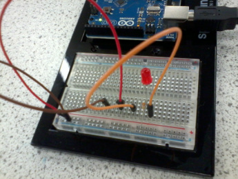
The protoboard that comes with the Arduino kit is much smaller then the ones I have been using in uni but works in exactly the same way. At first I struggled to push the components into it through fear of breaking them. They are a lot tougher then I was expecting.
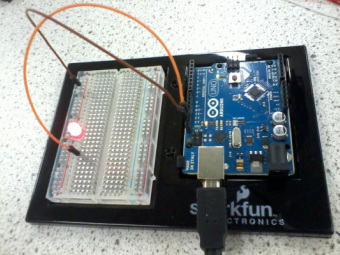
The Arduino kit that I bought came with little circuit overlays. I chose not to use these and just follow them instead.
