S2 Create and interpret circuit diagrams
Initial knowledge/skills rating *
September 2011
As an apprentice I made simple circuits diagrams using components like batteries, bulbs resistors and capacitors. I drew up wiring diagrams for circuits in series and parallel. I can remember some of the symbols and probably how to interpret a simple circuit diagram but I really need to refresh my memory.
I would love to look in my old text books but unfortunately against my better judgement and before I realised my next step on life’s path, I threw away my books…Big regret! Note to self, listen to your instincts even if you cannot justify them to other people. Also get over mistakes, leave regrets behind and work out how to move forward.
I will look at BBC Bitesize which will at least offer me knowledge to GCSE level and see how much I can remember.
Creating circuit diagrams for Spidy
(my spider money box for my systems and control project)
16th February 2012
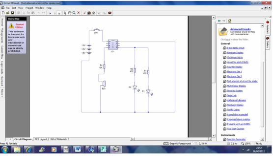
I started making very simple circuit diagrams using Circuit Wizard and Yenka. At first the circuits consisted of nothing more than a battery, resistor and bulb. I was trying, with the help of simulation programs, to remember little things: like which way round a battery symbol goes, which is the positive, which is the negative and what feeds what. I was just trying to remember the logic of it all. Little by little it all started to come back. But I think I have never done anything very complex before so I have a lot to learn.
I started making very simple circuit diagrams using Circuit Wizard and Yenka. At first the circuits consisted of nothing more than a battery, resistor and bulb. I was trying, with the help of simulation programs, to remember little things: like which way round a battery symbol goes, which is the positive, which is the negative and what feeds what. I was just trying to remember the logic of it all. Little by little it all started to come back. But I think I have never done anything very complex before so I have a lot to learn.
Before long I was trying to apply Dean’s tuition along with what I had remembered in order to create a circuit for my systems and control project. I wanted to make an electronic spider money box using a microprocessor in the form of a Picaxe chip. At first I planned on using two LED’s for spider’s eyes, which I could run in parallel directly from an output from my 08M2 pic chip. Just using one output seemed a little bit of a waste of my Picaxe chip so I decided to add a piezo and have a musical output as well.
Developing the electronics for Spidy
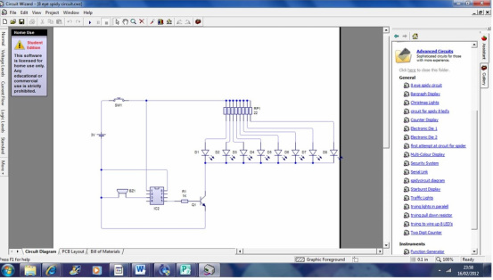
I thought I had everything sorted until I made a visit to Maplins to buy discrete components for my project. When I spotted tiny little red LEDs, 3mm diameter instead of the standard 5mm ones I realised I could trade my two LEDs for eight and make a single cluster of eyes just like a real tarantula. I couldn’t resist. I was also able to replace the 3AA batteries for a 3V cell battery. I was told the holder would accommodate two batteries should I require them. I wanted to change the batteries so that they would take up less space. I wanted to contain the power source within my money box; the more compact the power source, the more space I will be left to use for money storage. I really love these design changes even though I will need to set about changing my wiring diagram, I think it will be worth it.
As the packs of ten 3mm LEDs did not display a value I approached a member of staff. I was told the voltage value of the resistors sold in the packs were unreliable. I was advised to buy them separately with specific voltage guaranteed. Eventually they located some in the warehouse. They only carry a stock of one or two of each LED in the store and only a dozen or so at the warehouse. How strange, I would have expected a lot more. It will pay me to remember that you cannot just nip out and buy loads of components, even ordering them may have been difficult. However I have placed my order and am looking forward to their arrival.
In the meantime I must modify my wiring diagram and calculate the resistor values. I was advised of a value but I think it is wrong. Mind you the shop assistant was also trying to tell me I needed a 22.5v power supply for ten 2.5v LEDs. I knew that was wrong for a start. For a split second I believed him, till I thought wait a minute that is almost a car battery. What I actually need is for my LEDs to be powered in series that way 2.5 volts will be delivered from my 3v or 6v battery to each LED.
Errors
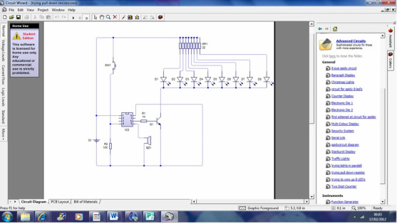
It has suddenly occurred to me that if my switch is only engaged for a small amount of time as a coin passes over it, no current will be available to operate the system. My switch, of course, needs to form an input into my pic chip where the pulse of electricity when the switch is activated acts a signal to the Picaxe processor to carry out the program I will have written.
I have also added a resistor in series with the switch to encourage electricity to flow through this part of the circuit. I am not quite sure why a resistor would have that effect, but that is what I have understood from my taught session. I must look into this. I hate getting my facts wrong and I like to understand why things work the way they do.
I have also added a resistor in series with the switch to encourage electricity to flow through this part of the circuit. I am not quite sure why a resistor would have that effect, but that is what I have understood from my taught session. I must look into this. I hate getting my facts wrong and I like to understand why things work the way they do.
17th February 2012 ***
With the circuit diagram I created for my spider money box a success, I feel happy that I would be able to share what I now know. So I have increased my skills rating to three stars.To pick up more skills rating stars I need to broaden my understanding. I would be happy to progress to the next level by creating more complex wiring diagrams or maybe just looking at some existing ones so that I can work out what is going on in them. I have an old electronics text book by Oliver and Boyd . This may be a good place to start.
I have experienced more circuit diagrams during taught sessions and they are becoming a little more complex with things like a Darlington pair. I have started creating circuits using the protoboard taken from Electronics by
Oliver & Boyd. These are simply circuits but I really believe I am someone who needs to start with the basics, fully understand them and build my knowledge up from there. I am not sure if there is any other way of learning. I do not see how you can progress if you do not have a good grasp of the basics.
Oliver & Boyd. These are simply circuits but I really believe I am someone who needs to start with the basics, fully understand them and build my knowledge up from there. I am not sure if there is any other way of learning. I do not see how you can progress if you do not have a good grasp of the basics.
Everyday Practical Electronics magazine
Saturday 17th March.
I was working at the Aldrich Library today looking at journals. When I came across an electronics magazine and flicked through the pages, my first reaction was I don’t understand this (I admit I was tied). Then I thought well actually lets break it down. I looked at the circuit diagrams and thought well actually I can name most of the components and I know what they do. I started looking at the projects and realised I would be able to tackle them. Well this is certainly a change of heart from when I started the course. I am looking forward to increasing my knowledge over the coming weeks.