S12 Create fault finding, test and calibration procedures
Initial skills ratings *
September 2011
I do not think I have ever calibrated anything electrical. Testing and fault finding? Not that I can remember.
I do not think I have ever calibrated anything electrical. Testing and fault finding? Not that I can remember.
Taught session **
4th November 2011
I have been turning my lecture into a Word document. The first two pages cover a fault finding procedure that can be used as a visual check of an assembled PCB. It is easy for very common errors and inexperienced soldering to cause problems to an otherwise sound design. I just wish my IT skills were better! This process is so slow for me. As for where I go from here to improve my skills and knowledge rating I will need to put the theory into practice.
I have been turning my lecture into a Word document. The first two pages cover a fault finding procedure that can be used as a visual check of an assembled PCB. It is easy for very common errors and inexperienced soldering to cause problems to an otherwise sound design. I just wish my IT skills were better! This process is so slow for me. As for where I go from here to improve my skills and knowledge rating I will need to put the theory into practice.
9th January 2012
One light stops working....but only sometimes?
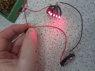
When I assembled the eight ultra bright LEDs for my spider money box I checked they were working as little sub-assemblies before joining them all together. everything appeared to be in good working order even after they were mounted in the spiders head.
After a few days one of the bulbs stopped working.
After a few days one of the bulbs stopped working.
First I carried out a visual check. I thought perhaps one of the legs had come un-soldered but the joints appeared good.
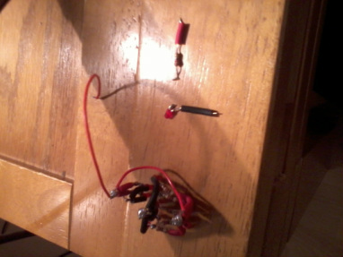
To remove the broken LED I needed to unsolder several LEDs. I thought once they were apart I would be able to identify the offending bulb easily because after all it was not working. What I found was that one disassembled bulbs were now working. Why? What was going on? Reassembled the same problem occurred. I started to worry that I was going to damage the LEDs keep taking them apart and re-assembling them.
This time I marked the broken bulb and once again when disassembled it appeared to work. I got tied of using the protoboard and started to take a short cut holding the componenets in my hand. I am sure it was more by luck that it went out and came on again whilst I was holding it. I then realised as I moved one LED of the LED I could make the bulb go on and off. All I can think is that the leg once inside the plastic LED dome had a faulty connection. This is a fault that cannot be detected by eye and did result in the circuit being dismantled. I replaced the bulb and everything worked fine
This was an intermittent fault within the component that cannot be detected by eye and did result in the circuit being dismantled. I do not know if I had contributed by cutting the legs so close to the bulb. Now that I am a little more experienced I would leave the legs a little longer just in case.

I replaced the bulb and everything worked fine...even if they are a bit on the bright side.
Spidy
July 2012
Whist making Spidy I encountered my own problems as did my peers working around me. A common error that other people made was to connect their batteries to their Pic-chip circuits with the polarisation the wrong way round which resulted in burnt out chips. Not good! Another problem I heard was the batteries had been left in a battery holder the wrong way round. Because they did not check the battery box assembly they assumed their project did not work. The fault was discovered and all was well but it does highlight the problems of not checking the basics. Look for the obvious first especially before dismantling anything major.
I had some problems with my soldering of the switch. Even though I was using a core solder (solder that contains flux) the solder would not take to one leg of the switch. If I had been at home I would have used an additional dab of flux but with none available I just persisted. Even after successful joining the wire would not stay in place. I started experiencing problems once I had programmed my circuit. Some times the circuit was behaving as if the circuit was complete when it should not have been. Eventually the fault was traced back to the switch. As I had used so much solder it had over many attempts run inside the switch and joined the connections.
I guess the main thing with electronics is look for the obvious by following the fault finding procedure as outlined above. This must be completed before connecting your circuit to a power supply. If once connected to the power supply your PCB does not work repeat the fault finding procedure. If the circuit still does not work start looking for the less obvious faults before taking everything apart.
I will only be giving myself a *** skills rating at this point as I would like to gain a lot more confidence in this area. I will only gain confidence with experience and awareness of the experience of others. It may pay me to take a look at YouTube as I find this such an easy way to learn.
