R6 Joining techniques
Initial skills rating **
September 2011
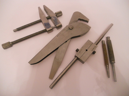
I made these tools as part of my engineering apprenticeship. I have used a variety of permanent and temporary joining techniques. The engineers clamp (far left) uses two threaded bars to join the clamp jaws as does the tap wrench (third from the left). The pipe wrench has a temporary component making a pivot whereas the hardened jaws are joined by rivets. Once the rivets were filed flat they were no longer visible.
I made these tools as part of my engineering apprenticeship. I have used a variety of permanent and temporary joining techniques. The engineers clamp (far left) uses two threaded bars to join the clamp jaws as does the tap wrench (third from the left). The pipe wrench has a temporary component making a pivot whereas the hardened jaws are joined by rivets. Once the rivets were filed flat they were no longer visible.
In my life I have used many different methods of joining resistant materials using both temporary and permanent methods of fixing:-
Temporary methods I have used to join metal:
· Nuts and bolts.
. Self-tapping screws
· Threads – I have cut both internal and external threads
Permanent methods I have used to join metal:
· Rivets – I made hand tools such as the pipe wrench when I was an apprentice.
· Pop rivets - used for joining thin sheet material
· Soldering - used to join stained glass windows. I have used the copper foil method associated with Tiffany lamps. I have also used soldering to join lead cane work and zinc cane.
· Silver solder for silver jewellery, using a mixture or easy and hard solder. I understand the principles of using different solders.
· Brazing – used while I was at school to join a little enamelled beaten metal work pot and dove tails on a brass jewellery box
· Soldering electrical components onto PCB’s
· MIG Welding (Metal inert gas welding)
· TIG welding (Tungsten inert gas welding)
· Arc welding
Temporary methods I have used to join plastic:
· Ratchet rivets
· Male and female nylon spacers.
Permanent methods I have used to join plastic:
Plastic adhesive - melts the two surfaces freeing the polymers to mingle and as the adhesive evaporates at room temperature the new bond forms permanently joining the two surfaces together.
The best thing I discovered through experimentation was that even when placed in an oven the bond between the two plastics was not broken.
Temporary methods I have used to join wood:
· Nuts and bolts
. Coach bolts
· Wood screws
Permanent methods I have used or helped students use to join wood:
· Panel/veneer pins
· Pop rivets through thin bendy ply (not what they were intended for but it worked)
· Dowels
· Mortice and tenon joints
· Comb joints
· Housing joints
I would like to practise my wood joints as I have never really done these from start to finish.
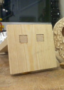
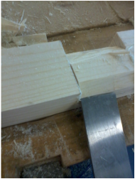
BISCUIT JOINTING
What can I say?
What an easy successful little technique that was, not that I have actually glued mine together yet. But that was no harder than using a jig saw. I was able to join two pieces of wood with a perfectly flush finish. I wish they had had one of these at Tanbridge. How much easier it would have made Rachel’s or Scott’s GCSE projects. They would have achieved a much better finished with a lot less effort. The Biscuit jointer is definitely a hand tool to be remembered.
It would be nice to test the joints for strength at some point, if I could find a comparable way. I may have to settle for a logical approach but it is worth thinking about.
MIG WELDING
Today I entered the heat treatment room with Dean and few others to attempt to weld for the first time in a very long time. I was as nervous as can be. I hadn’t had the best time on the computers and here I was about to attempt something I have not done for years. Sometimes I feel as if I am expected to be brilliant at things or at the very least, good but the way I view myself is very, very, differently. Did I blag my way onto this course? No, I don’t tend to big myself up. Did I lie about my experience? No. But what am I doing here? I feel terrible.
I have only ever used this type of welding equipment once for a joint about 25mm long, surely that doesn’t count. I attempted using a MIG welder when my children were at school. At first I couldn't cope with the speed and feed of the welding rod. It fed through so fast it was no longer suitable to weld with. This was totally new to me. I couldn’t see anything through the face guard and to my embarrassment and to the amusement of my daughters and their teacher I started to weld the crocodile clip holding the metal instead of the metal itself. These memories of this uncomfortable experience only added to my fear.
I was excited by the development of light sensitive welding masks that detect the light increase with the welding spark and close down the visibility. Wow! At least I should be able to see where the metal is this time.
Before I knew it I had the welding torch in my hand, spark had ignited and I couldn’t really see where I was meant to be welding but what was my right hand doing? It was like it had a mind of its own drawing giant circles in the air. As I lifted my visor I could see a little caterpillar like portion of weld crawling away from the joint. Perfect little circles of weld about the right size. I know they were crawling away from the join but hey they weren’t bad! I mean, if I could see what I am doing next time and keep the welding rod in the right place , maybe I will get this thing cracked.
A few days later one of my peers and I entered the heat treatment room to give the forge a go. Whist waiting for it to heat up we thought it would be good to have another go at welding. I seemed to be able to see through the visor a little better this time though I still think perhaps I need to lean in a little closer. I had about three small attempts. The first was like a curly caterpillar. The second was more attached to the top piece of material than the bottom piece so it would not have formed a strong joint but the third appeared to have melted both the top and bottom pieces of material together. The weld had a good uniform cross section. Another peer made the comment that there appeared to be a lot of weld but maybe it would be better when cleaned up. I wasn’t so sure, it was looking right to me. Admittedly taking a wire brush did improve its appearance and I think what I had done was about right. At least it reminded me of the welding I had done many years before. It would have been nice to do some more but other people wanted to use the equipment.
19th November 2011 ***
I have had time to reflect on my MIG welding experience and I think it would be a good thing to practise while I have the chance. Welding is not something people generally do well as it takes some practise to perfect your technique. Although I may never have to do any welding again it would be a good thing to learn. As I have previous experience of a different kinds of welding it should not take me long to improve my MIG welding skills.
In all honesty I have only just typed up this page up from my notes and I am just wondering why I gave myself such a low skills rating. I guess I just felt a bit nervous as it had been such a long time since I used some of these skills but the truth is it is amazing how it all comes back to you. Sometimes with a bit of an error on the way but it is all there ready to be jogged back to the surface.
My next step is to continue refreshing my memory because I am sure it will not take much to build my confidence.
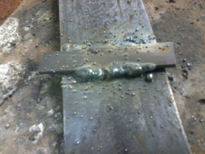
I have actually decided not do any more welding as the MIG welder being used is being used without any gas. I believe this is why there is so much splatter around the weld.
Silver Soldering
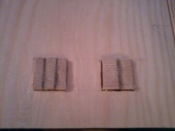
Both my samples of silver soldering look about the same but
were made using two different techniques.
the first method I tried was the rod method. Having mixed the flux to a watery paste about the thickness of single cream, I brushed it over the surfaces to be joined. I heated both pieces of metal before introducing the silver solder rod. I did not experience any of the problems Dean had warned us about. Apparently if the solder is introduced before the parent metals have reached a temperature sufficient to keep the solder molten when it hits their surfaces you can be left with large lumps of solder that does not flow to make a successful joint.melts away from the solder rod but solidifies when it hits the metal surface the solder is introduced before the metal has reached a high enough temperature the solder can drop off leaving big lumps of unmelted solder. The solder ran beautifully making a neat little joint. Was this beginners luck? Maybe but somehow I think it was more down to transferable skills from jewellery making classes.
Pleased with the results I wanted to try the second method where the joint was made by adding little pallions of silver solder along the edges to be joined. This was a little trickier. It is important to dry the water from the flux before the metal and solder can be heated to make the joint. Unfortunately it is very easy for the metal and the pallions to move out of place at this stage. Eventually, after putting the metal ba My joint was successful.
I found it easier to make a joint using silver solder rod rather than pallions. With pallions you have to estimate how much solder is needed in advance and placing the little pieces in place very tricky.
It would be nice to make something larger and with a purpose next.
Cutting threads
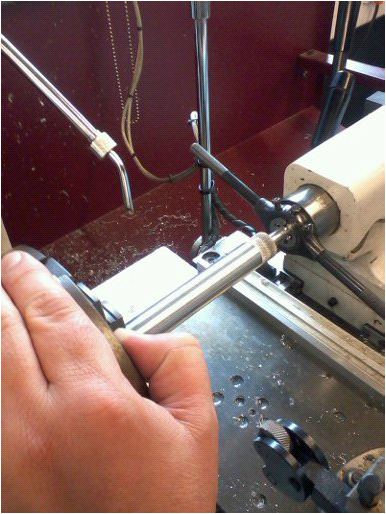
I was impressed I remembered the Zeus book and managed to identify what type of ISO thread the dies were. It is amazing the way things come back to you when you need them.
I did like the tip Dean gave me about using the tail stock on the centre lathe to position the die at right angles to the bar. This was a much easier way of starting the thread. I have only ever cut threads with the metal clamped in a vice before. It can be very difficult keeping the die at right angles to the bar while you get the thread started. Of course if the die is not at right angles you will not be able to cut the thread successfully.
I did like the tip Dean gave me about using the tail stock on the centre lathe to position the die at right angles to the bar. This was a much easier way of starting the thread. I have only ever cut threads with the metal clamped in a vice before. It can be very difficult keeping the die at right angles to the bar while you get the thread started. Of course if the die is not at right angles you will not be able to cut the thread successfully.
Wednesday 23rd November 2011
My first Mortice and Tenon joint
Yesterday the panic set in, I had been ill and had absolutely no one to confer with. Working drawings are due in tomorrow for my design and make project and although I know about the joints used for GCSE woodwork , I felt I had no clue about suitable joints for my project.
I tried the internet, D&T GCSE revision guide and YouTube but wasn’t getting the results I considered professional enough for my project. I dashed to our local library and picked up a couple of books that contained the most amazing, beautiful, wood joints I had ever seen, not to mention stunning projects. I selected the joints I thought would be suitable but they look so complicated I don’t think I can do them. I am freaking out about the whole project. WOOD scares me!
I presented my efforts to Bhav, half hoping she would say silly me I had chosen the wrong joints. No I had got it right. I agreed they are very beautiful but pleaded I won’t be able to do them. Bhav just very calmly said ‘you will’. We discussed a few ideas and I set to attempting my first multi Tenon joints.
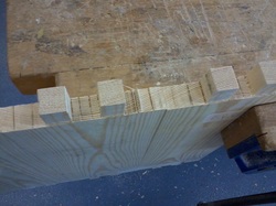
Having cut the square holes on the morticer, (having first set up the new mortise bit using a 2p piece to set the gap on the mortise drill and the outer cutter) I Cut two prongs known as tenons to match. They took me ages! Les showed me how to use the flat side of the chisel so that I was not digging in and removing too much material. I struggled at first to remove any wood but started to get the hang of it. A bit of advice from Lance regarding how easily my joint should go together and hey presto my first Tenon.
Not bad, room for improvement. I had measured the length of the Tenon to match the width of my wood but when assembled my Tenons are about a millimetre too short. Next time I need to add another millimetre or two and sand them back to have a flush finish. Les even described a more advanced decorative technique by adding little wedges of a dark hardwood into the Tenons. They sound very beautiful and I would love to give them ago. It looks like there are many ways to tackle the same job.
Not bad, room for improvement. I had measured the length of the Tenon to match the width of my wood but when assembled my Tenons are about a millimetre too short. Next time I need to add another millimetre or two and sand them back to have a flush finish. Les even described a more advanced decorative technique by adding little wedges of a dark hardwood into the Tenons. They sound very beautiful and I would love to give them ago. It looks like there are many ways to tackle the same job.
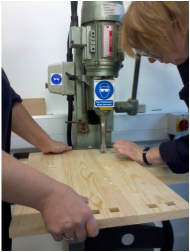
I moved onto the real thing. The most difficult part at this stage is the marking out. It really pays to take your time and work accurately Any errors become magnified from here. If marking out is sloppy there is nothing you will be able to do to improve your work. I took into account accumulative errors at this stage. Rather then using a datum hole or edge as I may do for metal I chose to position each pair of holes from the middle of each length of wood. I wanted my holes to appear centrally and I felt this was the most accurate way of achieving that.
My next difficulty was lining up the mortice chisel and bit. This has to be done by eye.
My next difficulty was lining up the mortice chisel and bit. This has to be done by eye.
I have decided not to mark up the tenon joints from my drawings because the inaccuracies that will have occurred as I lined up the mortice chisel and bit by eye will mean the tenons do not line up. Instead I have used the moticed holes to transfer positions for the tenon joints. (See R5 marking out techniques)
I used a tenon saw as much as possible because I wanted to improve my woodwork skills using hand tools. Although this will have taken longer than using the bandsaw I was surprised how quickly I cut them out. The Tenon saw gives a really square cut.
To my surprise and delight I did not need to do very much adjusting when I came to fit all the joints together. By wrapping a bit of aluminium oxide paper around a file I was able to remove any little bits of wood that were preventing the sides fitting together easily.
I am going to add a little veneer to my finger joints just to help tie in the dark wood that I am using for the sliding shelf. I found out if I had wanted to add little dark wedges I would have needed to have cut the tenon joints with angled sides rather than at right angles so that when the wedges are placed in they expand the tenon joint to make a tight fit.
This time all the little tenon joints protruded through the side panels of the bedside cabinet. The little gaps around them have yet to be filled and sanded.
30th December 2012
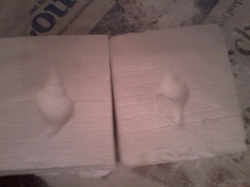
Pewter casting experiment
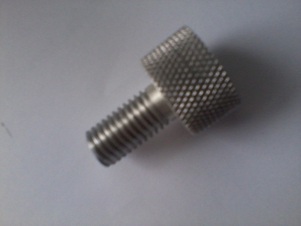
I thought it would be worth seeing if I could encase the head of a screw in pewter to make something like a little door knob. If successful I would use them to hang jewellery from for my design and make project.
Making a mould
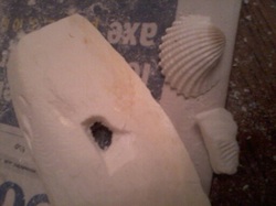
I started by cutting a piece of cuttle fish in half. Smoothing one surface using a piece of wet and dry paper. I then started to press the shell I had collected on a beach walk into the cuttlefish. Although this is how all the books I have ever read say this is how to make an impression. In reality the cuttlefish did not like being compressed. I tried again by scraping a little bit of cuttle fish away and then just pressing the shell in enough to take the details from the shell. I repeated this process overhand over until I was able to sink the whole of the shell into the cuttle fish.
Making a mould
I started by cutting a piece of cuttle fish in half. Smoothing one surface using a piece of wet and dry paper. I then started to press the shell I had collected on a beach walk into the cuttlefish. Although this is how all the books I have ever read say this is how to make an impression. In reality the cuttlefish did not like being compressed. I tried again by scraping a little bit of cuttle fish away and then just pressing the shell in enough to take the details from the shell. I repeated this process overhand over until I was able to sink the whole of the shell into the cuttle fish.
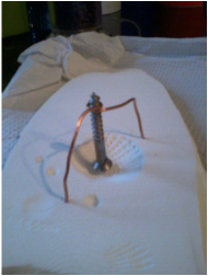
Positioning the screw
The screw was held in place using a little piece wire recycled from a small off cut of single core electrical cable. I stripped the outer insulation from from the wire so that it would push into the cuttle fish easily. By suspending the head of the screw into the cavity of the cuttle fish I was able to accurately position it in the middle of what would become pewter. This is important so that the screw head will not poke through the decorative front nor will it be so close to the rear surface that it pulls out easily.
The screw was held in place using a little piece wire recycled from a small off cut of single core electrical cable. I stripped the outer insulation from from the wire so that it would push into the cuttle fish easily. By suspending the head of the screw into the cavity of the cuttle fish I was able to accurately position it in the middle of what would become pewter. This is important so that the screw head will not poke through the decorative front nor will it be so close to the rear surface that it pulls out easily.
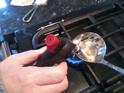
I found a new use for the gas hob, soup ladle and jewellery soldering torch and a small piece of lead free pewter I had bought earlier. As lead free solder melts at 245 degrees Celsius it melted quickly and easily. I was happily surprised my stainless steel ladle cleaned up as good as new too. All in all a much more enjoyable use of the kitchen facilities.
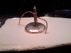
Having poured the molten pewter into the mould I allowed it to cool slowly and thoroughly before removing it from the cuttle fish. this way I would not get burnt but the molecular structure would have a chance to reform and become really solid before it was disturbed. It did not take very long.
I have made a perfect little component that could easily be recycled by melting the pewter and removing the stainless steel screw as the melting point of stainless steel is above 1400 degrees Celsius depending on the grade. Even a low grade of stainless steel like 304 melts at 1400-1450 degrees Celsius. In fact I did reject the largest and smallest castings and reused the pewter in this way. Even though I wanted the slight variation in sizes so that the product looked hand made. I thought some knobs looked nicer than others. The proportions were ascetically pleasing and the edges were pure shell detail rather then a rounded over spill of pewter.
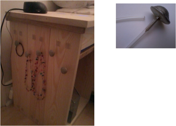
By screwing a little piece of clear flexible plastic tube over part of the screw thread I was able to leave enough thread to screw into my bedside cabinet. The little portion covered by the plastic tube provides protection for the jewellery from the thread.
I was so pleased with the results i even used one as a handle for the sliding shelf. The fine detail of the shell left in the cuttle fish mould was transferred perfectly transferred to the surface of the pewter. I will definitely use this technique again.
I was so pleased with the results i even used one as a handle for the sliding shelf. The fine detail of the shell left in the cuttle fish mould was transferred perfectly transferred to the surface of the pewter. I will definitely use this technique again.
Pewter casting mould using Kasier Lee Board
13th January 2012
I was so pleased with the results of my earlier success I wanted to make a large handle for the drawer of the bedside cabinet. This time I wanted to use a larger shell that would be too big for the cuttle fish even if I had another one but I had run out.
Instead I wanted to experiment with Kasier Lee board. A Board I had found for glass casting. I had read that it could be used for making moulds for the glass in this same way as I made them in the cuttle fish.I figured as the melting temperature of pewter is well below that of glass the mould should work.
I made the mould in two halves in the same way as I had with the cuttle fish. I made the first mould until about half of the shell lay inside the board and then started working away at the second half until one half of the mould sat neatly on top of the other with the shell enclosed inside.
Oh dear I realised when the shell is removed there is no way of lining the two halves of the mould back up. I cut four small pieces of thin wooden dowel into short lengths so that they could press into the Kaiser Lee board so that they would act as location pins when the shell was removed. This was working but the dowel made such a large hole in the crumbly Kasier lee board that I switched to thin piece of metal rod. I am so glad I have had years of buying things for hobbies and DIY and saving bits of recycled materials. It really makes improvising easy.
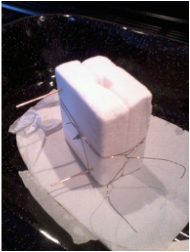
With the mould complete and the two halves together I wired them closed. I was ready for the pewter.
But sadly the molten pewter just ran out the bottom and the sides of the mold. I had been so focused on the differences of working with Kaiser Lee board and cuttle fish that I had not even noticed the surface texture of the man-made board. Of course the pewter was going to run straight out.
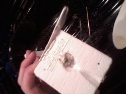
Not wishing to be beaten I filled the horizontal grooves with wood filler and waited for it to dry before smoothing the surface with wet and dry paper.I repeated the casting process and this time it worked. I had made a pewter handle.
The surface of this pewter shell was far less detailed than the shells I had cast in cuttle fish. There had also been a little seepage around the edge of the casting where the two halves of the mould had come together but not quite sealed. I liked the texture of the shell body: it was as if it had been sand blasted but if I filed away the spurs I would be left with a smooth line around the shell. I decided not to use it for my project. I can always reuse the pewter as I did for some of the other shell handles. The melting temperature of pewter is much lower then that of the steel screw. So to recycle the pewter all you need to do is heat the whole handle and remove the screw when the perter is molten.
The surface of this pewter shell was far less detailed than the shells I had cast in cuttle fish. There had also been a little seepage around the edge of the casting where the two halves of the mould had come together but not quite sealed. I liked the texture of the shell body: it was as if it had been sand blasted but if I filed away the spurs I would be left with a smooth line around the shell. I decided not to use it for my project. I can always reuse the pewter as I did for some of the other shell handles. The melting temperature of pewter is much lower then that of the steel screw. So to recycle the pewter all you need to do is heat the whole handle and remove the screw when the perter is molten.
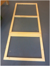
Making a frame for the activity board
I have never made a frame before and anything my husband did was screwed together. I think i will take a look in my Collins Woodworking Manual again.
Halving joints
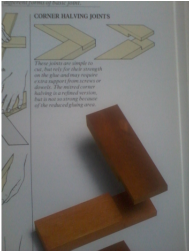
Although there are many joints I could use to make corner joints I need to consider how much strength I require and how long I want to spend making the frame.
This is not a piece of furniture where strength and appearance may be important. It is more about mounting a board away from the wall so that the fixings do not dig into the wall. I want to add some rigidity to the large ply wood board. I mainly expect the forces applied to it would be compressive and even those will be minimal. I have chosen joints that will be relatively quick and easy to produce. Nothing fancy just functional.
On the corners I will use halving joints. These will provide the maximum gluing area and will be strengthened when the ply board is secured to the frame using a screw on the corner.
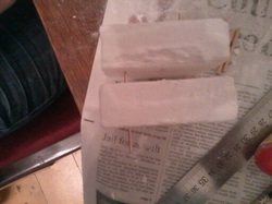
'T' halving joint
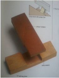
For the cross members I am going to make 'T' halving joints. These are very similar to the halving joints except they occur along the length of the wood rather than at the corners They divide the thickness of the wood into two where they join. Any changes in the frame thickness will be easy to accommodate.
Marking out was relatively easy. Using a Tenon saw was equally easy to cut half way through the thickness either side of the wood to be removed but i had no real idea of how to chisel out the middle without causing it to split off in large chunks. Luckily there is someone on our course that has trained as a carpenter so I was able to call on his expertise for advise.
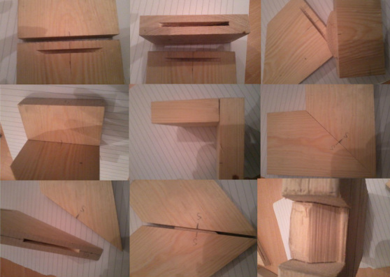
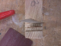
With the wood firmly secured in a vice and the flat side of the chisel uppermost you remove thin layers of wood working towards the middle. Turning the wood in the vice the same procedure is repeated and starts to look like the example in the photograph opposite. Because the angle of the chisel is against the wood the chisel travels upwards rather than digging into the wood.
With the wood firmly secured in a vice and the flat side of the chisel uppermost you remove thin layers of wood working towards the middle. Turning the wood in the vice the same procedure is repeated and starts to look like the example in the photograph opposite. Because the angle of the chisel is against the wood the chisel travels upwards rather than digging into the wood.
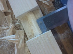
Turning the chisel over thin layers of wood can be can removed from the middle section. As the flat side of the chisel works across the surface a flat base is left behind. Wow that was so easy when I knew how. I ploughed through the remaining joints all in one session. But I was so into what I was doing I forgot to take any pictures.
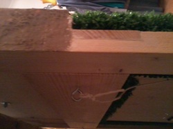
This photograph shows the mid section of the activity board where the frame changes in cross section so that the grass board could be inset. I do not want he grass to protrude into the path of the balls falling from the posting tube.
I was surprised how easily the frame went together. It is important to use a try square to ensure it goes together square. I also measured across the corners whist doing up the clamps to make sure nothing moved out of place. The worst thing I did was picked out some screws out of the wrong part of the box and started screwing the board to the floor. After that i laid out the fixings so I would not make the same mistake again.
I also rejected one piece of wood that I had been sold. I had not notices how bowed it was at the time. It was a very knotty piece of wood and I assume the forces within the wood were less uniform than if the wood had been knot free. I think if I had tried to use this piece of wood making the frame square would have been a lot more difficult.
I also rejected one piece of wood that I had been sold. I had not notices how bowed it was at the time. It was a very knotty piece of wood and I assume the forces within the wood were less uniform than if the wood had been knot free. I think if I had tried to use this piece of wood making the frame square would have been a lot more difficult.
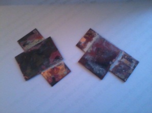
July 2012 *****
These are the photographs of my first biscuit joints. They should have been posted here months ago but I did not have the IT skills to do so. I want to put them here now because they are an important record of my progress. I even have a picture of my attempt to cut a halving joint in recycled wood. The wood split off in one large chunk when I was chiselling away at it. It did not matter at the time because only waste from the joint broke away. However I was aware I needed to learn to have some control over the wood. this is something I now know how to do.